The first sign that a chemical line is losing control is rarely a burst pipe. It is a valve that still turns but no longer shuts off, or a handle that now needs two hands to move.
On a 55 °C hydrochloric acid transfer line, a carbon steel ball valve can pit through in months, and 316L stainless trim begins to lose seat geometry as chlorides attack the body and the stem area. Each of those changes breaks the link between handle position and actual flow. That is the working definition of lost flow control.
UPVC (unplasticized polyvinyl chloride) and CPVC (chlorinated polyvinyl chloride) valve bodies remove that corrosion path completely. Both are thermoplastics with no electrochemical corrosion mechanism, so a body correctly rated for the fluid keeps its bore, its seat and its operating torque. What they do not remove is the need to match material, temperature, pressure and valve type to the duty.
Where Metal Valve Bodies Lose Flow Control
A metal valve stops controlling flow long before it leaks, because corrosion alters the seat, the stem torque and the effective bore while the body is still structurally intact.
Austenitic stainless steels such as 316L depend on a passive chromium oxide layer. Chloride ions break that layer down locally, producing pitting and, in a range of service combinations above roughly 60 °C, chloride stress-corrosion cracking. Hydrochloric acid, hypochlorite dosing lines and chloride-rich brine are the classic cases. The decline is not linear: a valve can pass its leak test at commissioning and fail to hold a static head eighteen months later.
The standard engineering answer is a higher alloy, often a nickel-based grade or titanium. That solves the corrosion question and creates three new ones: capital cost multiples of the thermoplastic alternative, long lead times for castings, and a galvanic couple wherever the alloy body meets carbon steel pipework.
Thermoplastic bodies change the picture in three ways that matter for control:
- No electrochemical corrosion, so bore diameter and seat geometry stay as manufactured.
- No galvanic couple with steel pipework, so no accelerated attack at the flange face.
- A smooth bore, typically quoted at around 0.0015 mm absolute roughness for PVC, which resists the scale and biofilm build-up that narrows a flow path.
You cannot actuate your way out of a corroded body. Material selection sets the ceiling on flow control; the actuator only decides how fast you reach it.
UPVC or CPVC: The Temperature Line Decides
UPVC suits continuous service up to about 60 °C, and CPVC extends that ceiling to roughly 93 °C at a reduced pressure rating.
Both materials are PVC-based. CPVC is produced by post-chlorinating PVC resin, which lifts the chlorine content from about 57 percent by weight to roughly 67 percent. The additional chlorine raises the glass transition and heat deflection temperatures, which is why a CPVC body holds its shape and its seat load at temperatures where a UPVC body would begin to soften and creep.
60 °C Continuous service ceiling for PVC-U valve bodies
93 °C Typical PVC-C ceiling, at a derated pressure
0.35-0.45 Indicative allowable-pressure factor near 90 °C
The two materials overlap heavily on chemical resistance. Dilute and moderate concentrations of sulfuric, hydrochloric and phosphoric acid are handled by both. CPVC extends the acceptable range at elevated temperature and carries more margin against oxidizing media such as sodium hypochlorite. Where the process stays below 60 °C and budget rules, UPVC remains the more economical body.
Depth of comparison matters at selection stage; a detailed material comparison of UPVC and CPVC valves is worth reading before the specification is frozen.
Property comparison for UPVC and CPVC valve bodies; temperature ceilings assume pressure is derated accordingly.
| Property |
UPVC |
CPVC |
| Chlorine content by weight |
About 57 percent |
About 67 percent |
| Continuous service ceiling |
About 60 °C |
About 93 °C, derated |
| Behaviour above 60 °C |
Allowable pressure falls steeply |
Retains more margin |
| Best fit |
Water treatment, ambient and warm chemical transfer |
Hot chemical, hypochlorite, hot process water |
| Relative body cost |
Lower |
Higher |
Which Valve Type Delivers the Control You Need
Match the valve type to the duty: ball valves for tight shutoff, butterfly valves for large-bore isolation, diaphragm valves for dirty or throttling service, and check valves for backflow protection.
Ball valves: shutoff and capacity
A quarter-turn ball valve gives bubble-tight shutoff with the lowest pressure drop of any isolation type, because a full-port bore matches the pipe internal diameter. Because flow area scales with the square of the bore, a full-port body passes roughly twice the flow of a standard-port body of the same nominal size at the same pressure drop. That capacity is a shutoff advantage, not a throttling one: a part-open ball seats abrasive particles against the seal and invites cavitation damage.
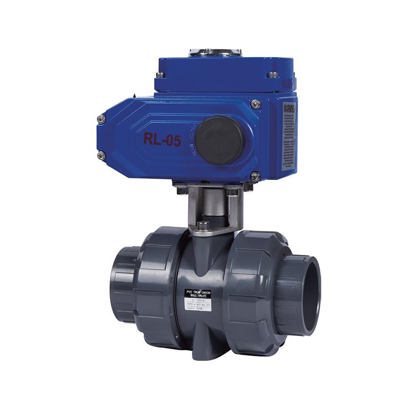
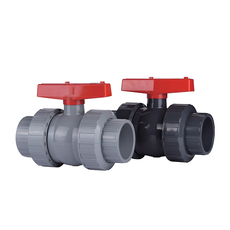 SCH80/DIN UPVC/CPVC Type I Industrial Ball ValveQuarter-turn ball valve with low fluid resistance and leak-free sealing, available in DN15–DN100 for chemical, water-treatment and HVAC pipelines.View Product →
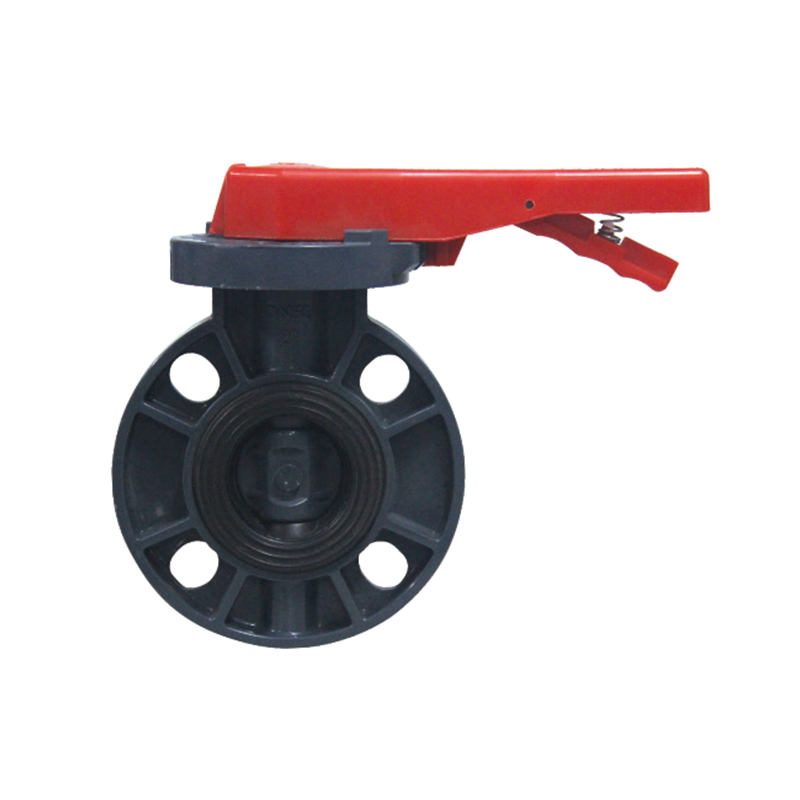
Above roughly DN100, a butterfly valve is the economical isolation choice. The disc sits in the flow path at all times, so a permanent pressure drop is designed in, and the disc edge becomes an erosion point in slurry service. Wafer and lug bodies save space; gear operators give a mechanical advantage that a lever cannot on a 10-inch disc.
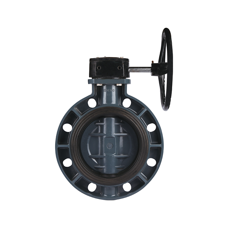 UPVC/CPVC Gear-Operated Butterfly Valve for Large PipelinesGear-operated UPVC/CPVC butterfly valve in DN160–DN400, suited to water treatment, chemical processing and HVAC lines where larger isolation valves need reliable sealing.View Product →
Diaphragm valves: the mechanism stays dry
A weir-type diaphragm valve keeps the working parts out of the fluid, which makes it the default choice for slurries, crystallising solutions and dosing lines that need partial opening. The diaphragm is a wear part with a defined replacement interval, and the weir profile limits capacity compared with a ball valve of the same size.
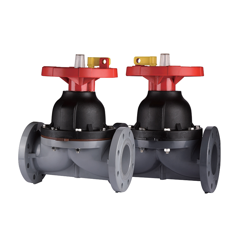 SCH80/DIN UPVC/CPVC Flanged Diaphragm ValveFlanged UPVC/CPVC diaphragm valve for corrosive liquids and gases, available DN25–DN125 with manual or pneumatic operation and DIN/ANSI/JIS flange options.View Product →
Check valves: protecting the rest of the loop
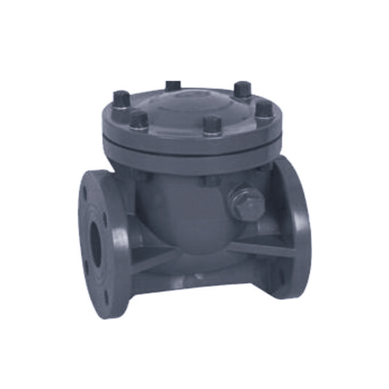
A ball check suits vertical runs and low-flow lines where a swing check would chatter; a swing check offers lower pressure drop on larger horizontal lines. Place it downstream of the pump discharge and upstream of any dosing injection point, so backflow cannot contaminate the dosing skid.
Isolation duty
Full-port ball valve on lines up to DN100, gear-operated butterfly valve above it. Prioritise bubble-tight shutoff and a bore that matches the pipe.
Throttling duty
Diaphragm valve for dirty or crystallising media, or a characterised control valve. A partly open ball valve is a wear strategy, not a control strategy.
Derating Turns a Headline Rating Into a Working Limit
A thermoplastic valve rated 150 psi at 23 °C may hold well under half of that at 80 °C, so the pressure-temperature chart, not the headline number, defines the real working limit.
Thermoplastics creep under sustained load, and allowable stress falls as temperature climbs. ISO 15493 sets out how PVC-U, PVC-C and ABS piping components are derated for temperature in industrial applications, and manufacturers publish pressure-temperature charts built on that logic. The pressure figure printed largest on a datasheet is the 23 °C value.
Indicative allowable-pressure factors for PVC-C valve bodies by temperature; treat as a trend only and confirm against the manufacturer's published pressure-temperature chart.
| Temperature |
Indicative factor |
Practical reading |
| 23 °C |
1.00 |
Full published rating applies |
| 40 °C |
About 0.80 |
Minor correction on most lines |
| 60 °C |
About 0.65 |
Recheck surge allowance |
| 80 °C |
About 0.45 |
Resize or step up a pressure class |
| 93 °C |
About 0.35 |
Edge of PVC-C capability |
The factors above are indicative engineering estimates for comparison, not a manufacturer rating. Add a surge allowance on top of the derated figure: pump shutoff head plus the transient rise from fast valve closure is the number to design against, and a solenoid-actuated ball valve closing in under a second generates a larger surge than a gear-operated butterfly.
Procurement note
Request the pressure-temperature chart for the exact body compound and seat elastomer, not the product family. Two valves that look identical in a catalogue can carry different ratings because of compound cell class and seat material.
Sizing and Interface Details That Decide Whether the Valve Fits
A valve that meets the pressure rating but not the flange drilling or the face-to-face dimension will not install, so DIN and ANSI details belong in the enquiry rather than on site.
ANSI B16.5 Class 150 and DIN PN10 or PN16 flanges share a bolt count on some sizes and differ on others, and the bolt circle and hole diameter rarely match exactly. Thermoplastic valves are offered drilled to either pattern, so the drawing must state which one. The same applies to wall thickness: an ASTM Schedule 80 valve end does not match a DIN metric series pipe end, even where the nominal diameter agrees.
For throttling duty, a working rule is to size so that normal flow falls between 20 and 80 percent of the valve's capacity, which keeps the plug or diaphragm off both extreme ends of its travel. For isolation duty, size to line velocity and check the resulting pressure drop at design flow.
Finally, joint cure. Solvent-cemented joints are governed by ASTM D2855, and cure time scales with pipe diameter and ambient temperature. A 2-inch joint needs hours, not minutes, before pressure testing; testing a green joint is the most common cause of a weeping flange that gets blamed on the valve.
What to Verify Before You Release a Valve Purchase Order
Six documents and details decide whether a thermoplastic valve order runs without surprises.
- Pressure-temperature chart for the exact body compound, seat and diaphragm elastomer.
- Compound cell class to ASTM D1784, such as 23447 for chlorinated PVC and 12454 for unplasticized PVC, quoted on the certificate.
- Flange drilling standard and face-to-face dimension stated on the drawing, not implied.
- Actuator torque quoted with a margin at the maximum operating temperature, since torque demand rises as seals stiffen.
- Shell and seat test records, plus NSF/ANSI 61 listing where the line carries potable or process water.
- Spare diaphragms, seats and O-rings specified by material, with a stated replacement interval.
Valve ratings for special engineered components in PVC and CPVC systems are covered by ASTM F1970, which is the specification to cite when a buyer needs a rating basis beyond a catalogue page. ZHEYI Pipeline (Wuhan) Co., Ltd. states ISO 9001-certified production across two manufacturing centres and supplies UPVC and CPVC valves drilled to DIN or ANSI patterns for chemical, lithium and water-treatment projects; the manufacturer's product range lists ball, butterfly, diaphragm and check bodies with pneumatic and electric actuation options.
Installation and Actuation Practices That Keep Control
Five field practices preserve the flow performance the valve was selected for.
- Support the valve independently. A thermoplastic body is not a pipe support and will deform under unsupported span loads.
- Align flanges before tightening, then torque bolts in a cross pattern to the gasket manufacturer's figure. Over-torque crushes the gasket face and distorts the body.
- Cure solvent-cemented joints fully per ASTM D2855 before any pressure test, and never use the valve to pull a misaligned pipe run into place.
- Stroke pneumatic and electric actuators through the full range at operating temperature, and set the open and closed limits on the actuator, not on the lever.
- Keep an upstream Y-strainer or basket filter ahead of every diaphragm and check valve, and clean it on a fixed interval rather than on failure.
Direct Answers to the Questions That Decide the Order
Do UPVC and CPVC valves give the same flow capacity?
Yes. For the same nominal size and port style, a UPVC and a CPVC valve of identical geometry have the same bore and the same flow coefficient. The difference is temperature capability and allowable pressure at that temperature, not capacity at 23 °C.
At what temperature should a process switch from UPVC to CPVC?
Plan the switch at 60 °C. Above that line, UPVC allowable pressure falls steeply while CPVC retains useful margin up to roughly 93 °C, provided the pressure is derated according to the manufacturer's pressure-temperature chart.
Can a CPVC ball valve be used for throttling?
Only briefly and at low differential pressure. A part-open ball exposes the seat to accelerated wear and, in cavitating service, to erosion of the ball surface. For continuous throttling, use a diaphragm valve or a characterised control valve sized so normal flow sits between 20 and 80 percent of capacity.
Which standard backs a CPVC valve pressure rating?
ISO 15493 defines the derating framework for PVC-C industrial piping components, and ASTM F1970 covers special engineered valves in PVC and CPVC systems. The binding document for a specific purchase remains the manufacturer's pressure-temperature chart for that body and seat combination.
 +86-15258772971
 dinys009@163.com

 English
 한국어
 Español
 عربى